So as I just finished my build a few weeks ago, I've noticed that my ECU setup is not original, but generally VERY badly documented.
I run a 2002 WRX ECU (from a manual, not that it matters) with the CarBerry Speed-Density Grp N ROM. It's wired into my stock harness, as my engine is an EJ251 with an M62 on it. It is completely functional, and flashed through the OBDII just like a normal WRX.
Standard blah blah disclaimer: I claim no responsibility for the damage done to your engine, your turbo, your love life, your driver's license or wallet. Just the psyche. :blol:
A large amount of this information comes from Carbotron, who did this and has most of the info. His car was older ('97L) and the wiring was completely different, however, so I had much work to do to transfer it to the RS' pinout.
This is my first point: DO NOT RELY ON PINOUTS. Trace wires, octuple-check against the WIRING DIAGRAMS. It saved my ass more times than I care to mention when things were either left off or incorrect on the pinout.
First, there are some mechnical requirements that you need:
![]()
![]()
![]()
Now, in MY case, I did it a little differently. The engine I got was pulled from a friend's crashed 2000 Legacy, and it had all of the cam/crank and IACV/TPS requirements cleared. Apparently some older Subarus used the more modern setup, but I can only verify the 2000 Legacy (2.5). The IM is different, though, as is the wiring, so use the RS stuff.
The wiring itself is pretty straightforward. Most of it is just cut & solder, and in lots of cases the wires are even the same color. I'll include a spreadsheet I made for 2000 RS to 2005 WRX harness. The only difference between the '02-'03 and '04-'05 harnesses that we care about is that two of the ECU connectors swapped numbers, the pins are the same. The harness I used for the ECU pigtails was from a 2005, so my numbers reflect that. If you have an older harness:
2002-3 Conn.
A: B134
B: B135
C: B136
D: B137
E: B84
2004-5 Conn.
A: B134
B: B135
C: B137
D: B184
E: B136
Yep. That's it, just to make it *THAT* much more confusing.
Now, to the notable issues.
The first thing you'll run into is the IACV difference. The '00RS IACV has SIX wires. One is power, one ground, the rest are what I believe to be individual steps in the solenoid's travel. The WRX IACV is only 3 wires, power, ground, and signal. I just chose one of the RS IACV wires and used that. DON'T cut the rest of the wires, they'll be very useful later.
Next, the MAP/IAT sensor. I only include this because it's likely if you're looking at this ECU swap, it's because BOOST. On the RS, the MAP AND the IAT are one sensor. If you're using the stock MAP and IAT, then it's just the pins in the spreadsheet at the ECU end. If, like me, you're changing the MAP sensor (I used a GM 2-BAR for my build), you'll need to do a little wire juggling. First off, the MAP/IAT is four wires. The pins are as follows, from the left to the right if you're looking at the connector.
1-Ground. Shared between the MAP and IAT. This should be left connected as standard.
2-IAT signal. This is just a thermistor, so for it to function, only pins 1 & 2 are required.
3-5V power. Shared across many sensors. Required for the MAP.
4-MAP signal. You need pins 1 and 3 hooked up for this to work.
Obviously, if you plan on using a different MAP or IAT, you'll need to cut and redirect those wires to your sensors. I used the stock IAT, the MAP wires are just cut short, and the harness wires lead to my GM sensor.
The Front O2 sensor is next. On the '00 RS, it's an OBDII-tricky twin-signal thing, and it's a sort-of half-wide-band. Real PITA. It's 6 wires, and one of the wires in the O2 connector isn't actually connected to the sensor, it's got some odd voltage divider circuit going on. Since I had a complete WRX harness, I just took the O2 sensor connector off it, and spliced that in, since it's four wires and done.
Basically, the four wires contain some badly worded signal wires. According to the FSM, there's Signal 1, Signal 2, Signal + and Signal -. The 2005 FSM says the Sig 1 and 2 are actually the heater wires. Signal - is just the shared sensor ground. Honestly, even the wiring diagrams are unhelpful at this point. Since all but the power and ground RS O2 sensors wires are inside a shield, I just traced their colors, and voltmeter'd the ground/power lines. I don't actually know which pins were which ATM, this is one place where my spreadsheet fails. I will check my actual pinouts tomorrow.
Now we come to the real PITA, the ignition coils. This was the worst part for the others who did this setup. In Carbotron's case, he ended up using LS CNP coils. I know someone else used diodes. I tried the diodes and had no luck, it only ever ran on two cylinders (fired the coil half as often as necessary). I actually tried some really weird stuff, but that's for my build thread.
Anyway, the way I got it to work was by using an OR Gate. This is a digital logic circuit, that took the two individual ECU outputs and fire the coil for either. I built mine out of parts I had laying around, since I couldn't get a complete one locally. I'll give you the basic idea.
An OR gate has five pins. Power, ground, input 1, input 2, and output. I tapped the coil power & ground wires. Then....
ECU COP 1 -> OR Input 1
ECU COP 2 -> OR Input 2
OR Output -> 1 & 2 Coilpack Input (Pin 1 on coil)
This was repeated with a second OR Gate for the other pack (pin 4). If you get a commercial OR Gate, it will be in IC form, which is standardized. I recommend the NXP HEF4071BP,652 (Digi-key link). You only need one of these, it has four OR gates onboard and we only need two. I can give pin numbers for this chip.
Pin 7 - Ground
Pin 14 - Power (+12)
Pin 1 - WRX ECU Coil 1
Pin 2 - WRX ECU Coil 2
Pin 3 - OR Gate to Pin 1 on RS Coilpack
Pin 4 - WRX ECU Coil 3
Pin 5 - WRX ECU Coil 4
Pin 6 - OR Gate to Pin 4 on RS Coilpack
I should warn that I have yet to switch to this IC, so I can't speak for its resilience yet, my home-made gate is more robust but slower. You will need to repurpose two additional wires for the WRX ECU's two additional coil wires. I used the spare IACV wires, hence why I said not to cut them earlier.
Obviously, you can just take the simple solution and get some individual coil packs. Chevrolet LS packs work well, it's what Carbotron uses. The wiring on that would be best left to him to explain.
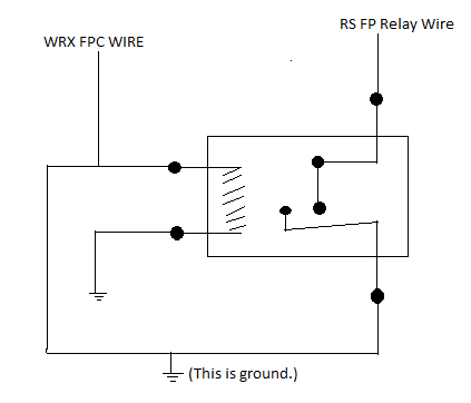
The next wiring weirdness is the Fuel Pump Controller. The WRX uses a PWM unit to slow the fuel pump when not in boost, for NVH and lifetime. I'm still using the stock RS pump, so I just wanted it ON. On the older cars, the fuel pump relay was controlled by switching the power side. On the newer cars (mine included) the relay is controlled by switching ground. That means Carbotron just took the FPC line from the ECU and used it to control his fuel pump relay, I couldn't do that. I had to add another relay, wired like this:
RS FP Relay to switched relay pin 1
WRX FPC wire to relay coil 1 AND switched relay pin 2
Relay switched pin 2 to ground
Relay coil 2 to ground.
Yes, the WRX FPC wire needs to be grounded to make this trick work. No, I can't explain that one. Here's a basic diagram, because this is weird:
![]()
I can try to explain this further if need be. The only "downside" to this setup is that it has no prime. As soon as the key is on, the pump is on. It might impact the pump lifetime, but that's it.
The final wiring to attend to is the OBDII port. I swear this one is easy, with one caveat. There's two "line end check" pins. BOTH need to be connected for flashing to work. The problem is that #2 is in the wrong place at the OBDII connector. It's in pin 5, it needs to be in pin 8. I found re-pinning to be really easy, the connector disassembles pretty simply, but I can explain it. The warning is that Subaru WIRES THE OBDII PORT BACKWARDS. I can't emphasize this enough. Basically, if you look up an OBDII port pinout online, you'll go crazy wondering WTF is wrong. Here's how it works, taken from SubieSMART:
So use the LOWER layout when re-pinning the OBDII connector, or else you'll go freaking insane wondering what's going on...
At this point you're through the worst of it. Now it's worth mentioning that you'll likely have a bunch of wires you won't need. All the TGV rubbish, Auto tranny gubbins, etc. In my spreadsheet, the things you can ignore are in yellow overlay.
This is the best I can remember right now. If I recall more, or Carbotron or one of the other four people who've done this have anything to add, please do!
My info is from all over, but thanks primarily to Carbotron and Brydon, whose harness info was indispensable. If you have a different year car, that thread will likely hold all the pin differences. Anyway, I'm out of info now. Maybe. :rolleyes:
I run a 2002 WRX ECU (from a manual, not that it matters) with the CarBerry Speed-Density Grp N ROM. It's wired into my stock harness, as my engine is an EJ251 with an M62 on it. It is completely functional, and flashed through the OBDII just like a normal WRX.
Standard blah blah disclaimer: I claim no responsibility for the damage done to your engine, your turbo, your love life, your driver's license or wallet. Just the psyche. :blol:
A large amount of this information comes from Carbotron, who did this and has most of the info. His car was older ('97L) and the wiring was completely different, however, so I had much work to do to transfer it to the RS' pinout.
This is my first point: DO NOT RELY ON PINOUTS. Trace wires, octuple-check against the WIRING DIAGRAMS. It saved my ass more times than I care to mention when things were either left off or incorrect on the pinout.
First, there are some mechnical requirements that you need:
- WRX Crank Sprocket. This is the (I think) 32-tooth sprocket, used on all EJs since '02 (and in some cases earlier). It's part number 13021AA141, looks like this:

- 2005 2.5RS Cam Sprocket. This is a little harder to see the difference when installed. The triggers on the back are different, the PN is 13019AA051. Looks like the one on the right (the left is the older style):

- WRX IACV, PN 22650AA181, or 22650AA182. Looks like this:

- WRX (or STi) Front O2 sensor.
- Any 5V MAP sensor (the stock RS one will do for NO boost).
- Any 5V MAF (if you want to run a standard WRX ROM). Unnecessary for the CarBerry Speed-Density ROM.
- Any 5V TPS (again, RS stocker is fine).
- Any IAT. The RS one WILL work, but the wiring is a touch odd. More on that later.
- OBDII port re-wire. Again, more on that later.
- Carbotron had to change his cam and crank position sensors, I didn't. He never confirmed if that was due to bad sensors or not.
Now, in MY case, I did it a little differently. The engine I got was pulled from a friend's crashed 2000 Legacy, and it had all of the cam/crank and IACV/TPS requirements cleared. Apparently some older Subarus used the more modern setup, but I can only verify the 2000 Legacy (2.5). The IM is different, though, as is the wiring, so use the RS stuff.
The wiring itself is pretty straightforward. Most of it is just cut & solder, and in lots of cases the wires are even the same color. I'll include a spreadsheet I made for 2000 RS to 2005 WRX harness. The only difference between the '02-'03 and '04-'05 harnesses that we care about is that two of the ECU connectors swapped numbers, the pins are the same. The harness I used for the ECU pigtails was from a 2005, so my numbers reflect that. If you have an older harness:
2002-3 Conn.
A: B134
B: B135
C: B136
D: B137
E: B84
2004-5 Conn.
A: B134
B: B135
C: B137
D: B184
E: B136
Yep. That's it, just to make it *THAT* much more confusing.
Now, to the notable issues.
The first thing you'll run into is the IACV difference. The '00RS IACV has SIX wires. One is power, one ground, the rest are what I believe to be individual steps in the solenoid's travel. The WRX IACV is only 3 wires, power, ground, and signal. I just chose one of the RS IACV wires and used that. DON'T cut the rest of the wires, they'll be very useful later.
Next, the MAP/IAT sensor. I only include this because it's likely if you're looking at this ECU swap, it's because BOOST. On the RS, the MAP AND the IAT are one sensor. If you're using the stock MAP and IAT, then it's just the pins in the spreadsheet at the ECU end. If, like me, you're changing the MAP sensor (I used a GM 2-BAR for my build), you'll need to do a little wire juggling. First off, the MAP/IAT is four wires. The pins are as follows, from the left to the right if you're looking at the connector.
1-Ground. Shared between the MAP and IAT. This should be left connected as standard.
2-IAT signal. This is just a thermistor, so for it to function, only pins 1 & 2 are required.
3-5V power. Shared across many sensors. Required for the MAP.
4-MAP signal. You need pins 1 and 3 hooked up for this to work.
Obviously, if you plan on using a different MAP or IAT, you'll need to cut and redirect those wires to your sensors. I used the stock IAT, the MAP wires are just cut short, and the harness wires lead to my GM sensor.
The Front O2 sensor is next. On the '00 RS, it's an OBDII-tricky twin-signal thing, and it's a sort-of half-wide-band. Real PITA. It's 6 wires, and one of the wires in the O2 connector isn't actually connected to the sensor, it's got some odd voltage divider circuit going on. Since I had a complete WRX harness, I just took the O2 sensor connector off it, and spliced that in, since it's four wires and done.
Basically, the four wires contain some badly worded signal wires. According to the FSM, there's Signal 1, Signal 2, Signal + and Signal -. The 2005 FSM says the Sig 1 and 2 are actually the heater wires. Signal - is just the shared sensor ground. Honestly, even the wiring diagrams are unhelpful at this point. Since all but the power and ground RS O2 sensors wires are inside a shield, I just traced their colors, and voltmeter'd the ground/power lines. I don't actually know which pins were which ATM, this is one place where my spreadsheet fails. I will check my actual pinouts tomorrow.
Now we come to the real PITA, the ignition coils. This was the worst part for the others who did this setup. In Carbotron's case, he ended up using LS CNP coils. I know someone else used diodes. I tried the diodes and had no luck, it only ever ran on two cylinders (fired the coil half as often as necessary). I actually tried some really weird stuff, but that's for my build thread.
Anyway, the way I got it to work was by using an OR Gate. This is a digital logic circuit, that took the two individual ECU outputs and fire the coil for either. I built mine out of parts I had laying around, since I couldn't get a complete one locally. I'll give you the basic idea.
An OR gate has five pins. Power, ground, input 1, input 2, and output. I tapped the coil power & ground wires. Then....
ECU COP 1 -> OR Input 1
ECU COP 2 -> OR Input 2
OR Output -> 1 & 2 Coilpack Input (Pin 1 on coil)
This was repeated with a second OR Gate for the other pack (pin 4). If you get a commercial OR Gate, it will be in IC form, which is standardized. I recommend the NXP HEF4071BP,652 (Digi-key link). You only need one of these, it has four OR gates onboard and we only need two. I can give pin numbers for this chip.
Pin 7 - Ground
Pin 14 - Power (+12)
Pin 1 - WRX ECU Coil 1
Pin 2 - WRX ECU Coil 2
Pin 3 - OR Gate to Pin 1 on RS Coilpack
Pin 4 - WRX ECU Coil 3
Pin 5 - WRX ECU Coil 4
Pin 6 - OR Gate to Pin 4 on RS Coilpack
I should warn that I have yet to switch to this IC, so I can't speak for its resilience yet, my home-made gate is more robust but slower. You will need to repurpose two additional wires for the WRX ECU's two additional coil wires. I used the spare IACV wires, hence why I said not to cut them earlier.
Obviously, you can just take the simple solution and get some individual coil packs. Chevrolet LS packs work well, it's what Carbotron uses. The wiring on that would be best left to him to explain.
The next wiring weirdness is the Fuel Pump Controller. The WRX uses a PWM unit to slow the fuel pump when not in boost, for NVH and lifetime. I'm still using the stock RS pump, so I just wanted it ON. On the older cars, the fuel pump relay was controlled by switching the power side. On the newer cars (mine included) the relay is controlled by switching ground. That means Carbotron just took the FPC line from the ECU and used it to control his fuel pump relay, I couldn't do that. I had to add another relay, wired like this:
RS FP Relay to switched relay pin 1
WRX FPC wire to relay coil 1 AND switched relay pin 2
Relay switched pin 2 to ground
Relay coil 2 to ground.
Yes, the WRX FPC wire needs to be grounded to make this trick work. No, I can't explain that one. Here's a basic diagram, because this is weird:
I can try to explain this further if need be. The only "downside" to this setup is that it has no prime. As soon as the key is on, the pump is on. It might impact the pump lifetime, but that's it.
The final wiring to attend to is the OBDII port. I swear this one is easy, with one caveat. There's two "line end check" pins. BOTH need to be connected for flashing to work. The problem is that #2 is in the wrong place at the OBDII connector. It's in pin 5, it needs to be in pin 8. I found re-pinning to be really easy, the connector disassembles pretty simply, but I can explain it. The warning is that Subaru WIRES THE OBDII PORT BACKWARDS. I can't emphasize this enough. Basically, if you look up an OBDII port pinout online, you'll go crazy wondering WTF is wrong. Here's how it works, taken from SubieSMART:
Quote:
|
The OBD2 standard illustrates the plug with the wide edge uppermost. \ 01 02 03 04 05 06 07 08 / \ 09 10 11 12 13 14 15 16 / But the Subaru wiring diagrams illustrate it with the narrow edge uppermost. / 01 02 03 04 05 06 07 08 \ / 09 10 11 12 13 14 15 16 \ |
At this point you're through the worst of it. Now it's worth mentioning that you'll likely have a bunch of wires you won't need. All the TGV rubbish, Auto tranny gubbins, etc. In my spreadsheet, the things you can ignore are in yellow overlay.
This is the best I can remember right now. If I recall more, or Carbotron or one of the other four people who've done this have anything to add, please do!
My info is from all over, but thanks primarily to Carbotron and Brydon, whose harness info was indispensable. If you have a different year car, that thread will likely hold all the pin differences. Anyway, I'm out of info now. Maybe. :rolleyes: